Friday, December 23, 2011

Polymers Identification

Objectives:

1. To identity the types of polymer by using water

2. To identity the types of polymer by using copper wire

3. To identity the types of polymer by using alcohol

4. To identity the types of polymer by using acetone

5. To identity the types of polymer by using oil

6. To identity the types of polymer by using heat

Introduction:

Polymers are long chain organic molecules that are assembled from many identical and smaller molecules called monomers. Polymerization of is the process to assemble all the monomers together in order to form a huge and complicated molecule.


image Monomer of high density polyethylene


imageMonomer of polyvinyl chloride


Polymer is containing many units of monomer in its long chain. When there is a lot of monomer joining together chemically, polymer is formed, which shown in the picture below:

image Polymer of high density polyethylene


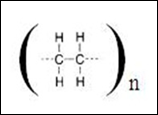
Generally, we can use the symbol below to show the structure of polymer instead of drawing the whole structure of polymer. Besides, we are not able to draw the whole structure because the number of monomer is usually over hundreds or even thousands of units.

The above picture refers to the simple structure in which it shows the whole structure of polymer or we named it as molecular formula as well.

The polymers shown in the picture above are the most common polymer that we always see and use in daily life. These includes polyethylene terephthalate (PETE), high density polyethylene (HDPE), polyvinyl chloride (PVC), low density polyethylene (LDPE), polypropylene (PP) and polystyrene (PS). These polymers are classified as class 1, followed by class 2, class 3 and so on. Identification of polymer by simply observing its appearance is difficult to differentiate them. However, we can identify them by using water, copper wire, alcohol, acetone, oil and heat.

Lassaigne's Test or Sodium Fusion test is also can be used to identify some of the polymers. For example, the presence of nitrogen, N in polyamides, and the presence of chlorine, Cl in PVC can be identified by using sodium fusion test. Besides, IR also can be used to identify the type of polymer via their major functional groups. The carbonyl stretches, O-H stretches, aromatic bends, etc could clearly show the identity of a polymer. Despite these test can be applied in identifying polymers, but today we only focus on the simplest test.

image

In this experiment, we will use some known plastic material and carry out some tests to identify the types of polymer. The flow chart below shows the overall tests on polymer identification.

image

We will use another three unknown sample of plastic to perform the test on them in order to identify the unknown samples.

Material:

Samples of polyethylene terephthalate (PETE), high density polyethylene (HDPE), polyvinyl chloride (PVC), low density polyethylene (LDPE), polypropylene (PP) and polystyrene (PS), three unknown samples of plastic, isopropyl alcohol, corn oil, copper wire, acetone

Apparatus:

Test tube, test tube rack, stopper, Bunsen burner, beaker, forceps, gauze wire

Procedure:

A) Water test

1. Pour 10ml of water into a test tube.

2. Place one of the samples into the water and stir the water by using a glass rod.

3. Observe whether the sample sink or float on the water surface.

4. Remove the sample from water and dry it for later use.

5. Repeat steps 1 to 4 by using each of the samples.

6. Take the samples that sank in the water for copper wire test while save the floated sample for alcohol test.

B) Copper wire test

1. Obtain a piece of copper wire about 6cm long and insert it into a small cork.

2. Burn the copper wire by using a Bunsen burner and heat until it is red hot.

3. Remove the copper wire from flame and touch on the sample of plastic. A small amount of sample should melt.

4. Place the wire copper with sample into the flame. A luminous flame is observed.

5. Repeat steps 1 to 4 by using the samples which sank in the water.

C) Acetone test

1. Prepare 20ml of acetone into a beaker under the fume hood.

2. By using a forceps, place the sample of plastic into the acetone for 15 seconds.

3. Remove the sample and press it firmly.

4. Scrape the sample to observe if the outer layer has softened.

5. Repeat steps 1 to 4 on the sample that gave yellow-orange flame.

D) Heat test

1. Prepare 100ml of water in beaker and heat it until boil.

2. By using a forceps, place the sample of plastic into the acetone for 15 seconds.

3. Remove the sample and press it firmly.

4. Scrape the sample to observe if the outer layer has softened.

5. Repeat steps 1 to 4 on the sample that shown negative result in acetone test.

E) Isopropyl alcohol test

1. Pour 10ml of isopropyl alcohol into a test tube.

2. Place one of the samples samples that floated on the water surface into the test tube and stir the water.

3. Observe whether the sample sink or float on the surface.

4. Remove the sample from water and dry it for later use.

5. Repeat steps 1 to 4 by using the samples that floated on the alcohol surface.

F) Oil test

1. Pour 10ml of oil into a test tube.

2. Place samples that floated on the alcohol surface into the test tube and stir the sample.

3. Observe whether the sample sink or float on the surface.

4. Repeat steps 1 to 4 on the unknown samples

Precaution steps:

1. Carry out the test under a fume hood.

2. Avoid the isopropyl alcohol and acetone from any sources of flame.

3. Hold the wire copper by using a forceps after heated.

4. Equip with personal protective equipment such as glove and mask.

Monday, December 19, 2011

Qualitative Analysis of Organic Compounds (Sodium fusion Test or Lassaigne Test)

Objective:

1. To carry out Lassaigne test in order to determine the elements (N,S halogens) present in the unknowns.

2. To identify the elements present in compounds and their colouration.

Introduction:

Qualitative analysis is always applied as a first step in identifying a compound when a new compound is readily prepared or isolated from some natural source. In an organic compound, elements carbon, hydrogen and oxygen are assumed to be present commonly. Nitrogen, sulphur and halogens (chlorine, bromine and iodine) may also present in the organic compound. The identification of elements in a given compound is a type of qualitative analysis since the experiment is dealing with the composition of a unknown compound. This experiment must be handled very carefully as further the analysis of the organic compound is according to the element present in it. Generally, the traditional technique is only can be applied to inorganic ions in aqueous solution.

When a new compound contains covalent bonding instead of ions, its molecule can be broken up into ions by controlled decomposition of the compound. The reagent used which cause the decomposition of the original unknown compound into the ions produced by the decomposition will reflect clearly those elements that were present initially in the compound. In this experiment, sodium fusion test (Lassaigne’s test) is used in elemental analysis of qualitative determination of elemental halogens, sulphur and nitrogen in a sample. Sodium is a very strong reducing agent that will able to break up the organic compounds carbon atom chain. It also will convert the atoms which are covalently bonded to the carbon chain to inorganic ions. The elements are detected by sodium fusion test. The organic compound is fused with metallic sodium to convert these elements into ionic mixture which dissolved in water and the filtrate is used to perform the tests.

The organic compound undergoes sodium fusion test which the carbon present in the particular compound is reduced partially to elemental carbon. The nitrogen present in the compound is reduced to cyanide ion, CN- while the sulphur present is converted into the sulfide ion, S2-. Any halogens (Cl, Br, I) that are present in the compound are reduced to the halides ions, Cl-, Br- and I-. A precipitate of an iron/cyanide complex with the characteristic of dark blue colour (Prussian blue) will be formed if cyanide ion is present in the compound. If sodium is not heated well, very little amount of cyanide ion is produced during fusion test. So, a greenish solid may result. It is always helpful to repeat the sodium fusion test in order to confirm the presence of nitrogen if only the greenish solid is being produced.

Several techniques can be used to test the presence of sulfide ion in the unknown organic compounds. Hydrogen sulfide gas will be produced if the filtrate obtained from sodium fusion products is acidified. This can be noted by the formation of lead(II) sulphate precipitate is formed after the lead(II) ions introduced into the solution.

image

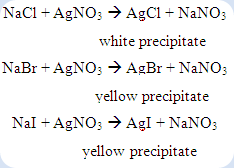
Besides, the sulfide ions can be tested by adding with sodium nitroprusside reagent. The formation of purple or violet colour shows the presence of sulfide ion. Silver ion reagent can be used to confirm the presence of halide ions in the compound. The formation of precipitate between halide ion and silver ion as shows below:

image

For the compound consists of more than one halogen, the mixed precipitate of silver halides can be observed as a result. However, it may be necessary to remove the cyanide ion and sulphide ion if they were present. Otherwise, these ions will precipitate with the silver ions to form precipitate which will mislead to the presence of halogens in the compound.

Apparatus:

Fusion tubes

Test tube

Evaporating dish

Gauze

Tongs

Materials

Sodium metal

Unknown organic compounds A,B,C

0.5M ferrous sulfate

0.5M ferric chloride

3M sulfuric acid

3M acetic acid

3M nitric acid

Sodium nitropusside

Lead acetate

0.1M silver nitrate

Procedure:

Part A: Sodium Fusion Test (Lassaigne)

1. 2-3 drops of unknown substance (for liquid) or 0.1g (for solid) was put into the fusion tube.

2. A piece of sodium was placed into the tube.

3. The tube was hold with a pairs of tong. The heating was gently to avoid spurting out of the sodium. When the sodium was molten, the compound was heated strongly until the end of the tube was red hot (continue heating for 1 minute).

4. The hot tube was plunged into 20ml of distilled water in a evaporating dish and covered with a gauze.

5. The tube was crushed with a pestle.

6. The mixture was filtered into a clean test tube. The colourless and clear filtrate was readily to be examined for the presence of nitrogen, sulphur, and halogens.

Part B: Test for nitrogen (Cyanide test)

1. To 1ml of filtrate, few drops of 0.5M ferrous sulfate was added and a dark green precipitate of iron(II) hydroxide is formed.

2. If sulphur is also present, precipitate will be black. More ferrous sulfate solution was added dropwise to precipitate all the sulphide ion until no more black precipitation is formed.

3. The mixture was heated to boiling with shaking, cooled and acidified with 3M sulfuric acid. If nitrogen is present, a blue colour (Prussian blue) appears immediately on addition of a trace of 0.5M ferric chloride solution.

Part C: Test for sulphur (sulphur test)

1. To 1ml of filtrate, a few drops of dilute solution of sodium nitroprusside were added. If sulphur ion is present, a deep purple colour will appear.

2. Alternatively, sulphide ion may be detected by precipitation as black lead(II) sulphide with lead(II) acetate solution which has been acidified by 3M acetic acid.

3. If halide is also present, white or yellow lead(II) sulphide precipitate may also formed.

Test for halogens

1. 1ml of filtrate was acidified with a few drops of 3M dilute nitric acid.

2. Silver nitrate solution was then added into the solution. Halides are indicated by the formation of a white or yellow precipitate.

Part E

The above procedure was repeated for unknown B and C. For each test, the observations were written down and the elements in the unknown were deduced.

Results:

Table 1 Observations of the unknown compounds on nitrogen test

Unknown

compound

Observation on nitrogen test

Inference

A

i) Some dark green precipitate and a little amount of dark precipitate were formed after brownish orange FeSO4 is added.

ii) The precipitate become greenish after more FeSO4 is added.

iii) The colour of precipitate remained unchanged after heating.

iv) The precipitate does not change after sulphuric acid is added.

v) Blue precipitate is formed immediately after adding of FeCl3

Nitrogen is present.

B

i) The solution turns to yellow after brownish orange FeSO4 is added.

ii) Brownish orange precipitate is formed after heated.

iii) Colourless solution is formed after H2SO4 is added.

iv) No change after FeCl3 is added.

Nitrogen is absent.

C

i) The solution turns to yellow after brownish orange FeSO4 is added.

ii) Brownish orange precipitate is formed after heated.

iii) Colourless solution is formed after H2SO4 is added.

iv) No change after FeCl3 is added.

Nitrogen is absent.

Table 2 Observations of the unknown compounds on sulphur test

Unknown

compound

Observation on sulphur test

Inference

A

a) Sodium nitroprusside

i) A deep purple solution is formed immediately.

b) Acidified lead(II) acetate

i) A black precipitate is formed.

Sulphur is present.

B

a) Sodium nitroprusside

i) A pale yellow solution is formed.

b) Acidified lead(II) acetate

i) A white precipitate is formed.

Sulphur is absent.

C

a) Sodium nitroprusside

i) A pale yellow solution is formed.

b)Acidified lead(II) acetate

i) A white precipitate is formed.

Sulphur is absent.

Table 3 Observations of the unknown compounds on halogens test

Unknown

compound

Observation on halogens test

Inference

A

Formation of white precipitate after nitric acid and silver nitrate are added.

Halogen is present.

B

Formation of white precipitate after nitric acid and silver nitrate are added.

Halogen is present.

C

Formation of yellow precipitate after nitric acid and silver nitrate are added.

Halogen is present.

Discussion:

The organic compounds to be analyzed consist of basically of a chain of carbon atoms which various other atoms are attached. Since these elements are covalently bonded to the carbon chain, it is unable to dissolve in water to form cations and anions. However, sodium fusion test can be used to reduce those atoms that are covalently bonded to the carbon chain to inorganic soluble ions since sodium is a very strong reducing agent. In the Lassaigne’s test, the nitrogen can be reduced to form cyanide ions, CN-:

image

For sulphur, it had been reduced to form sulfide ion, S2- in Lassaigne’s test as shown in the following:

image

If both nitrogen and sulphur are present in the organic compound at the same time, then the chemical reaction below will take place in the test:

image

If halogens (Cl, Br, I) are present in the compound, the halogens will be reduced to form halide ions (Cl-, Br-, I-) during the sodium fusion test.

image

The inorganic ions in aqueous solution could be easily observed after undergo certain tests which can indicates the presence of elements in the particular compounds.

In the cyanide test, the filtrate of compound A was added with ferrous sulfate, a dark green precipitate was formed. The formation of ferrous hydroxide was produced from the reaction between ferrous sulfate and sodium hydroxide.

image

The sodium hydroxide was formed by the reaction of unreacted sodium metal with water due to incomplete reaction of sodium fusion with compound A.

image

The FeSO4 solution was added to confirm the presence of NaOH and to react completely with it in the filtrate. At the same time, a small amount of black precipitate was formed at the bottom but it was disappeared after more ferrous sulphate was added. The formation of black precipitate may be due to the ferrous sulphide exists in the mixture.

image

The equation below shows that the ferrous sulphate was reacted with the sodium cyanide to form sodium ferrocyanide as the main product.

image

The sulphuric acid and increase in temperature was used to increase the suitable medium for the formation of complex. As a result, ferric-ferrocyanide complex with the colour of Prussian blue was precipitated out after ferric chloride is added to oxidize the Fe2+ to become Fe3+. This Prussian blue precipitate indicates that the unknown A contains nitrogen in the compound.

image

Some of the Fe3+ was formed before the oxidation of ferric chloride. This might be due to the air oxidation of iron(II) ions in the mixture before the ferric chloride is added. For compounds B and C, a negative result is obtained which end up with colourless solution as results. Hence, these shown nitrogen are absent in the both organic compounds.

The reduced sulfide ion can be confirmed by using two different tests which were sodium nitroprusside test and lead(II) acetate test. For the first test, the appearance of deep purple solution shows the positive result. The formation of sodium sulphonitroprusside is a complex that was formed between the sodium nitroprusside and sodium sulphide.

image

In another test, the black precipitate will be formed if the sulphur is present in the compound. The formation of black precipitate shows a positive result for this test.

image

The compounds B and C did not consisting sulphur in their structure because they cannot give the positive result on both tests. A pale yellow solution was formed after sodium nitroprusside was introduced and the solution shows the colour of sodium nitroprusside. In the latter test, white precipitate was formed may be due to the precipitation of the lead (II) ions with the halide ions. Based on the observation, the organic compound A containing sulphur while compound B and C did not containing sulphur.

In the halogens test, if white or yellow precipitation takes place after silver nitrate was added into the filtrate from compound A, B and, C respectively is known as the positive result. If cyanide ion or sulfide ion present in the compound, the acidified solution must be heated until boiled in order to expel the hydrogen cyanide gas and hydrogen sulfide gas. This step was taken to avoid the cyanide ions and sulfide ions cause the error in the halogens test. The sodium halide formed during the sodium fusion test was reacted with the silver nitrate to form the insoluble silver halide as precipitate in the solution.

image

The white precipitate was formed in the filtrate from compound A while yellow precipitate were formed in the both filtrate from the compound B and C. This is mean that the halogen presents in the compound A probably is chlorine whereas the halogens exist in the compound B and C were possibly bromine or iodine.

Precaution steps:

1. Safety glasses should be worn in the laboratory at all the time.

2. Do not add too much of water into the sodium fusion products unless if has been established with certainly that all elemental sodium has been destroyed.

3. The fusion of unknown compound is carried out in the fume hood.

4. When heating the liquids, use a small flame instead of large and move the test tube quickly through the flame.

5. The heating process of unknown compound must carried out in fume hood.

6. Avoid the corrosive sulfuric, nitric and acetic acids touch on skin because it can be dangerous to skin.

Thursday, December 15, 2011

The Use of Volumetric Flask, Burette and Pipette in Determining the Concentration of NaOH Solution

Objectives:

1. To carry out titration of a strong acid (HCl) with a strong base (NaOH).

2. To determine the end point of titration with the use of phenolphthalein as indicator.

3. To determine the concentration of base when the concentration of acid is known by doing calculations related to titration.

Introduction:

The main purpose of this experiment is to determine the unknown concentration of a known reactant. Volumetric analysis is a method of quantitative chemical analysis that always used in titration. The technique is carried out by using a reagent of a known concentration (standard solution) and volume to react with a solution where the concentration is unknown. There are various types of titration carried out for different purposes such as acid-base titration and redox titration. Within the acid-base titration, there are four types of reactions:

(1) titration involving a strong acid and a strong base

(2) titration involving a weak acid and a strong base

(3) titration involving a strong acid and a weak base

(4) titration involving a weak acid and a weak base

The titration carried out is the acid-base titration which is based on the neutralization reaction that occurs between an acid and a base to produce salt and water. The base is added slowly into the conical flask with acid until there are all exactly reacted. This is called the end point or also known as the equivalence point of the reaction.

The equivalence point of the neutralization reaction is the point at which both acid and base have been consumed and neither is in excess. In other words, the hydrogen ion and hydroxide ion concentrations are equal in the solution. In order to determine the equivalence point in a titration, acid-base indicators need to be added to the acid solution before the titration start. The end point of a titration is indicated when the indicator changes color. An indicator is a weak organic acid or base that has distinctly different colors in its non-ionized and ionized forms. This will be discussed further in discussion section. Different indicators show different colour changes at the same pH, therefore choosing of indicator for a particular titration depends on the acid and base used.

Hydrochloric acid (HCl) and sodium hydroxide (NaOH) is used as the reactants in this experiment. HCl is a monoprotic acid which dissociate to give out one H+ ion. Monoprotic acids have acid dissociation constant, Ka, which indicates the level of dissociation in water. Hydrochloric acid has large Ka value as it is a strong acid and dissociate completely in water. NaOH is a metallic base and ionic which composed of sodium cation and hydroxide anion. The hydroxide ion makes sodium hydroxide a strong base which reacts with acids to form water and corresponding salts.

Procedure:

  1. Volumetric flask was cleaned and rinsed with distilled water.
  2. 25ml of NaOH solution was transferred into the volumetric flask.
  3. The volumetric flask was topped up to 250ml with distilled water and rotated several times.
  4. Burette was cleaned with distilled water and rinsed with 5ml NaOH solution few times and was filled.
  5. Pipette was cleaned and rinsed a few times with HCl.
  6. 25ml of HCl solution was pipetted into 3 conical flasks.
  7. 3 drops of phenolphthalein was added into HCl solution.
  8. The initial and final readings of burette were recorded.


Result and calculations:

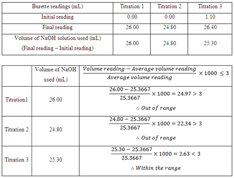
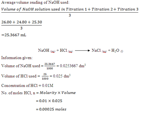
image


 image


image 

Discussion:

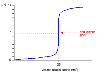
The titration of a strong acid and strong base in this experiment can be illustrated with a graph called a titration curve. It is a graph of pH versus volume of the solution titrated. The figure below represents the pH versus volume data of the titration curve for the HCl-NaOH titration. From the graph we may explain the chemical changes happen during titration and decide which indicators best to be used to determine the endpoint which matches the equivalence point of the neutralization.

image

Based on the graph, the pH has a low value at the beginning of the titration which shows the concentration of the HCl in conical flask. As the titration proceeds, the pH changes slowly until it reaches just before the equivalence point. At the equivalence point, the pH rises sharply by just adding only two drops of base. This is because when the equivalence point is reached, the number of moles of hydrogen ions and hydroxide ions is equal to each other; therefore a slight addition of base will result in a steep increase of pH. Beyond the equivalence point, the pH again rises only slowly. According to the graph, any acid-base indicator whose color changes in the pH range from about 4.0 to 10.0 is suitable for HCl-NaOH titration.

The acid-base indicator that is used for the titration of HCl-NaOH is phenolphthalein which is situated within the pH range of 8.3 to 10.0. Other indicators only have pH range within 1.0 to 8.8 which does not include the pH range beyond 9.0 as phenolphthalein where the pH range is until 10.0. Based on the interpretation of the graph, indicator whose color changes in the pH range from 4.0 to 10.0 is only suitable for the HCl-NaOH titration. Therefore phenolphthalein is chosen rather than the other indicators.

As we known an indicator is usually a weak organic acid or base that has distinctly different colour in its non-ionized and ionized forms, but what are the characteristics of an indicator that make let us determine the endpoint of a titration by showing different colours. Acid-base indicators exist in two forms, a weak acid represented as HIn and having one colour and its conjugate base represented as In- and having a different colour. The indicator does not affect the pH of the solution if only just a small amount of indicator is added to a solution. However, the ionization equilibrium of the indicator is affected by the concentration of H3O+ in the solution. When in a solution, the acid ionizes to the following ions:

clip_image032

Based on the Le Châtelier’s principle, increasing [H3O+] in the solution shifts the equilibrium to the left, increasing the amount of HIn and thus showing the acid colour. On the other hand, decrease in [H3O+] in a solution shifts the equilibrium to the right, increasing the amount of In- and hence displaying the base colour. In general, if 90% or more of an indicator is in the form HIn, the solution will show the acid colour. If 90% or more is in the form In-, the solution takes on the base colour. If the concentrations of HIn and In- are about equal, the indicator is in the process of changing from one form to the other and has an intermediate colour which is the mixture of acid and base colour.

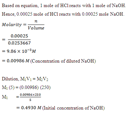
Based on the results obtained, within the three titration carried out only Titration 3 is less than 3 and within the range. However, Titration 1 and 2 is more than 3 and is out of the range. The causes of the results to be out of range can be due to human errors. First of all, the NaOH solution could have been diluted as the burette used to fill the NaOH solution is rinse with distilled water and not with NaOH before use. This causes the concentration of NaOH to be slightly different from the standard solution that has been prepared. The same possibility does happen to the conical flask which is used to fill the HCl which will be titrated against NaOH where the flask only rinse with distilled water not with HCl. Thus, the concentration of HCl may be less than 0.01M. Besides that, the reading on the burette could have some minor error because during the recording of readings the meniscus shown on the burette is not clearly view. In order to correct the error, a white paper should be situated behind the burette in order to have a clearly view on the position of the meniscus so that a more accurate readings can be obtained.

Precaution steps:

Firstly, is the determination of the titration end point which is based on the colour changing of the indicator added to the conical flask. Confusion arises about when to stop the titration as the colour changes is difficult to be observed. Therefore, a white tile or a piece of white paper should be placed at the bottom of the conical flask so that the changes of colour can be easily seen. Next, NaOH solution will react quickly with the carbon dioxide in the air. Therefore NaOH should be cover when it is not in use. This is the reason the prepared standard solution of NaOH is closed with the cap. Lastly is the dilution or the preparation of the standard solution of NaOH. The standard solution is prepared in a 250mL volumetric flask by adding 5mL of NaOH and distilled water should be added to the graduated line in the flask. During the adding of distilled water, water could have overshoot the line and cause the concentration of the standard solution to be different from the expected concentration. Thus, use dropper to fill the water into flask when the meniscus level approaches to the graduated line of the flask to avoid the overshooting of distilled water during the preparation of standard solution.

Monday, December 5, 2011

Determining Molecule Weight by Freezing Point Depression Method

Objectives:

  1. To determine the freezing point of a substance from its cooling curve.
  2. To study the effect of foreign substance content on the freezing point of a solvent.
  3. To determine the molecular weight by using the freezing point depression method.

Introduction:

When non-volatile solute is added into a pure solvent, the freezing point of the solvent is depressed. This phenomenon is called the freezing point depression. In other word, the solution possesses a lower freezing point than the pure solvent. The freezing point depression can be explained as solvent molecules leaves the liquid phase and join to form the solid phase; they leave behind a lesser volume of solution where the solute particles may present. This results in the decrease of entropy of the solute particles. Thus, we can say that freezing point depression depends on the concentration of the solute particles present and it is called colligative properties. The colligative properties are solution that depends on the number of molecules in a constant volume of solvent but not the properties of the molecules. However, when the concentration of the solute becomes larger, where the interaction of solute becomes more important, therefore, the freezing point depression may depend on certain properties of the solute rather than the concentration.

In this experiment, we will investigate the phenomenon of freezing point depression and determine the molar mass of substance X. The relationship between the lowering of the freezing point and the concentration of the solution is given by the following:

image

Methods:

A) Determination of the Freezing Point of Naphthalene

  1. A weighing boat was weighed.
  2. 5g of naphthalene was added to the weighing boat and weighted again.
  3. The naphthalene was transferred into a test tube.
  4. The naphthalene was melted using the water bath.
  5. When all had melted, the test tube from the water bath was dried and clamped on a retort stand and the initial temperature was recorded.
  6. The liquid naphthalene was stirred continuously and the temperature was recorded every 15 seconds until no more change in the gradient for the temperature vs. time graph.
  7. A graph of temperature versus time was plotted.
  8. The freezing point of naphthalene was determined.

B) Determination of the Freezing Point and Molecular Weight of a Substance

1. Approximately 0.5g of substance X was weighed.

2. The substance was added to the naphthalene in a test tube which was used in part A.

3. The melting and cooling steps were carried out.

4. The molecular weight of substance X was calculated.

[Kf for naphthalene is 6.8]

Apparatus and Materials:

  • Naphthalene
  • Substance X
  • Test tubes
  • Stopwatch
  • Beaker
  • Thermometer
  • Glass rod
  • Retort stand
  • Water bath

Results:

Part 1

Mass of weighing boat 1 = 2.5402g

Mass of naphthalene + weighing boat 1 = 7.5438g

Mass of naphthalene = 7.5438g – 2.5402g

= 5.0036g

Part 2

Mass of weighing boat 2 = 0.4515g

Mass of substance X + weighing boat 2 = 0.9502g

Mass of substance X = 0.4987g

Table 1: The temperature readings for naphthalene.

image

Table 2: The temperature readings for naphthalene and substance X.

image

Calculations:

image

Kf for naphthalene = 6.8 kg mol-1

Mass of substance X = 0.4987g

Mass of solvent in kg (naphthalene) = 0.0050036kg

image

Molecular weight of substance X = 677.55g mol-1

Discussion:

The application of freezing point depression is the determination of the molecular weight of the substance X. A weighed amount of the solute (substance X) is dissolved in a known mass of solvent (naphthalene). The freezing point of the solvent (the temperature at which solid and liquid phases are in equilibrium) is determined by the cooling of the solution. When the graph of the time versus temperature was plotted, a longest horizontal portion which is the constant temperature of the graph indicates the freezing of the pure liquid. However, a solution (mixture of substance X and naphthalene) will freeze over a range of temperature which is lower than the constant freezing point of the solvent (naphthalene). The plot will show a change of slope when solid solvent begins to form. The concentration of dissolved solute will steadily increases as the solvent freezes. This will cause the freezing point to continue decrease after the constant temperature. After obtaining the change of freezing point (∆T) and the value of Kf, then it is possible to calculate the molar mass of substance X.

Based on the graph plotted for the pure solvent (naphthalene), the freezing point obtained is 76.0oC. Whereas, the freezing point obtained for solution of substance X and naphthalene is 75.0oC. From the results obtained in the experiment, it obeys the theory of freezing point depression stating that the solution which contains naphthalene and substance X will have lower freezing point compared to the freezing point which contains only pure solvent (naphthalene). All the graphs used to determine the freezing point shows a staircase-like shape. For the graph of temperature versus time for naphthalene, initially, the temperature was 76.0oC and the temperature remained constant for more than 3 minutes. After that, the temperature continues to fall until the last second the time was recorded. The shape of this graph did not obtained like a staircase as the initial temperature start to become constant and continue to fall until the end of the experiment. During the starting of the experiment, the temperature of the solvent does not decrease because the solvent was not over heated in the water bath. Thus, the temperature measured in 0 second is the freezing point of the solvent. However, the graph for the solution of naphthalene and substance X exhibits a staircase-like shape. The initial temperature was 80oC then there is a slight decrease until it reaches 75oC, the equilibrium state of the substance which is the conversion of liquid to solid state. After that, the temperature will start to decrease until the end of the experiment.

The experimental freezing point was selected based on the temperature that remains the longest period for all the three different solution. This is because during this period, temperature do not rise until all the solid has melt as heat of fusion is taken up to convert the solid state substance to liquid state.

In order to make sure the results obtained obeys the theory, some of the precautions steps should be taken in order to prevent results error. Firstly, all apparatus used should be washed and rinsed thoroughly with distilled water to avoid contamination occurrence. Furthermore, during the solution is left to melt from solid to liquid, the content should be stirred in order to maintain thermal equilibrium. Uneven distribution of heat in the solution will caused the temperature obtained not accurate. Thus, the freezing point depression will be affected. In order to dispose the substances inside the test tube, the substances was melted in the water bath and disposed into the fume chamber.

Wednesday, November 23, 2011

Grignard Synthesis of Triphenylmethanol

Objective:

1. To synthesis triphenylmethanol from Grignard reaction

2. To study the method to produce Grignard reagent

Introduction:

Grignard reagents are organomagnesium halides (RMgX), and are one of the most synthetically useful and versatile classes of reagents available to the organic chemist. An alkyl, benzyl, or aromatic halide is reacted with a magnesium metal by using an anhydrous solvent in order to produce Grignard reagent. Ether or tetrahydrofuran are usually can be used as the anhydrous solvent in producing the particular reagent. Tetrahydrofuran is a strong base and it has a better solvating ability, it may used when Grignard reagent does not readily form in diethyl ether. This is considered as an organometallic compound which consists of the combination of a metal and organic molecule. Figure 1 in below shows the general reaction mechanism for the formation of Grignard reagent.

clip_image002

The chemical reaction between an organic halide and a magnesium metal can produce an alkyl or aryl free radical and magnesium free radical. The formation of Grignard reagent has been occurs. The bonding between carbon and magnesium is a covalent bond but it is highly polarized because the magnesium is bonded to halide which is an electron withdrawing group. This causes the formation of partial positively charge and partial negatively charge on the magnesium atom and alkyl or aryl group respectively. Hence, the carbanion has both characteristics of a good nucleophile and a strong base. Its basicity allows it to react with the electrophile carbon in a carbonyl group. Besides, Grignard reagent also works with acidic compound such as carboxylic acid, phenol, thiol, alcohol, and even water. One of the most important reactions is the addition of Grignard reagent to the carbonyl compound like aldehyde, ketone, and ester in order to produce the corresponding secondary alcohol and tertiary alcohol.

clip_image004

Figure 2

The most challenging part of this experiment is to avoid the Grignard reagent contact with water. The partial negative charge on the carbon atom that bonded to magnesium exhibits a very basic property. The water molecule will destroy the nucleophilic property of Grignard reagent. So, several precaution steps must be taken in the procedures to avoid the Grignard reagent reacts with water: the reaction flask is dried in the oven before use; iodine is vaporized in the flask tie up traces of water and to activate the surface of magnesium; the anhydrous diethyl ether should be used.

clip_image006

Figure 3

The figure 3 above shows the Grignard reagent and water reaction. The metal hydroxide (alkoxide) formed in the above reaction is appears as insoluble white solid (HO-MgBr or RO-MgBr) in the diethyl ether solvent. Thus, the process of producing Grignard reagent must be start over again in a dry glass if the insoluble white solid is observable during the formation of Grignard reagent.

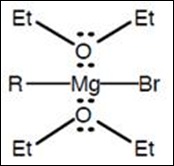
For a variety of reasons, anhydrous diethyl ether is the solvent choice for carrying out a Grignard synthesis. One of the reasons is the vapors of the highly volatile diethyl ether helps to prevent the oxygen in the atmosphere to reach the reaction solution. Grignard reagent will reacts with oxygen which hydroperoxides is produced. This compound is highly unstable if exposed to the air so that the compound is usually not isolated from the solvent. Other than that, the basic oxygen atoms in ether molecules are actually coordinate with and help to stabilize the Grignard reagent. The figure 4 below shows how the anhydrous diethyl ether protects Grignard reagent from oxidation:

clip_image008

Figure 4

There is a layer of oxide coated on the surface of magnesium which used to synthesis Grignard reagent. The oxide layer works to prevent it to react with alkyl bromide. The formation of Grignard reagent is highly exothermic which will produce a lot of heat energy from the system. Once the reaction has been initiated, the system will reflux itself in the bottom flask without any external heat source. The adding of a drying tube that contains calcium chloride to the reflux apparatus is used to protect the reaction from atmospheric moisture.

In this experiment, bromobenzene is the alkyl halide used to generate Grignard reagent.

clip_image010

Figure 5

Once the Grignard reagent is readily formed, the carbonyl compound has been introduced into the reagent in order to synthesis the expected product. The methyl benzoate (ester) acts as the carbonyl containing compound in the experiment. The reaction between methyl benzoate and Grignard reagent is showing in the following figure 6:

clip_image012

Figure 6

Dissociation of magnesium alkoxide produces a ketone which tends to react further with more Grignard reagent. The final step of the synthesis is involving hydrolysis of the magnesium alkoxide by using a mineral acid. As the result, the reaction synthesizes an alcohol, triphenylmethanol and magnesium salt (water soluble).

A side reaction may take place in the reaction between phenylmagnesium bromide and bromobenzene. The side product has been produced is biphenyl which consists of two phenyl rings. The biphenyl is known as impurity in the experiment. The impurity can be removed from the product through a method of recrystallization since biphenyl is much more soluble in ligroin compared to triphenylmethanol.

Apparatus: dropping funnel, two neck round bottomed flask, drying tube, condenser, sonicator, magnetic stirrer, hot plate, separating funnel, beaker, Buchner funnel, glass funnel, melting point apparatus

Materials: magnesium turning, anhydrous diethyl ether, bromobenzene, calcium chloride, methyl benzoate, iodine crystal, 10% H2SO4, ice, sodium bisulfate, sodium sulfate anhydrous, petroleum ether, methyl spirit

Procedure:

Part A – Preparation of phenylmagnesium bromide (phenyl Grignard reagent)

1. A condenser and a 50ml dropping funnel were set up to a 250ml two neck round bottom flask.

2. A calcium chloride drying tube was inserted into the top of the condenser.

3. 1.4g of magnesium turning was weighed and placed into the two neck round bottom flask with a stir bar. 10ml of anhydrous diethyl ether was added immediately into the two neck bottom flask.

4. 6.2ml of bromobenzene and 30ml of anhydrous diethyl ether were added into the 50ml dropping funnel.

5. 5ml of the mixture in dropping funnel was added to the ether/magnesium mixture. The mixture is stirred with a magnetic stirrer.

6. If the reaction does not begin immediately, both palms were placed around the bottom of the flask to keep it warm.

7. A small amount of iodine crystal was added directly into the magnesium surface if the reaction does not take place after 5-10minutes.

8. Once the reaction was initiated and the formation of Grignard reagent became steady, the ether refluxed itself. The remaining mixture in dropping funnel was added dropwise into the round bottom flask.

9. The solution was allowed to reflux for 10 minutes.

Part B – Preparation of triphenylmethanol from Grignard reagent

1. After reflux, the round bottom flask was cooled down in ice bath and a solution of 3.2 ml of benzoate dissolved in 15ml anhydrous diethyl ether was placed in the dropping funnel.

2. The solution was added over 5 minutes to avoid the solution to get too exothermic.

3. Once the reaction was completed, the solution was heated to reflux for 10 minutes to complete the reaction.

4. After reflux, the round bottom flask was cooled with ice bath and the mixture was poured into a 600ml beaker with contains 75g of ice and 30ml of 10% H2SO4.

5. The mixture was stirred until all white solid was dissolved.

6. The mixture was poured into the separating funnel and separated the two layers. The ether layer was washed with 15ml of H2SO4, followed by 15ml of water and then with a solution of 1g of sodium bisulfite dissolved in 12ml of water.

7. The ether layer was dried over sodium sulfate anhydrous and filtered with cotton wool. 15ml of petroleum ether was added to the ether layer. The ether layer was concentrated over a steam bath at 60-80 °C until the triphenylmethanol was formed. The product was cooled in an ice bath.

8. The product was recrystallized from methyl spirit.

9. The weight, yield and melting point of triphenylmethanol were determined.

Results and calculation

Weight of magnesium = 1.4009g

Volume of bromobenzene = 6.2ml

Volume of methyl benzoate = 3.2ml

Weight of watch glass = 14.8091g

Weight of watch glass + weight of product = 13.7410

Weight of product = 1.0681g

clip_image013

Atomic weight of magnesium = 24.31g/mol

Number of mole of magnesium = 1.4009 g / 24.31 g mol-1

= 0.0576mol

Molecular weight of bromobenzene = 157g/mol

Density of bromobenzene = 1.495 g/cm3

Weight of bromobenzene = density x volume

= 1.495 g/cm3 x 6.2cm3

= 9.269g

Number of mole of bromobenzene = 9.269g/ 157 g mol-1

= 0.0590mol

Since the magnesium is limiting reagent, so the number of mole of Grignard reagent produced is limited by number of mole of magnesium.

Number of mole of Grignard reagent produced = 0.0576mol

Density of methyl benzoate = 1.0837 g/cm3

Weight of methyl benzoate = density x volume

= 1.0837 g/cm3 x 3.2cm3

= 3.468 g

Molecular weight of methyl benzoate = 136.144g/mol

Number of mole of methyl benzoate = 3.468 g / 136.144g mol-1

= 0.0255 mol

Since the Grignard reagent is excess, the product is limited by methyl benzoate so that it is limiting reagent in the reaction.

Thus, the number of mole of triphenylmethanol = 0.0255 mol.

Molecular weight of triphenylmethanol = 260.318g/mol

Theoretical weight of triphenylmethanol = 0.0255mol x 260.318g/mol

= 6.6381 g

Actual weight of triphenylmethanol =

Percentage yield = actual yield / theoretical yield x 100%

= 1.0681g / 6.6381g x 100%

= 16.09%

Melting point of triphenylmethanol = 153°C ~ 156°C

Discussion:

The purpose of this experiment is to synthesis triphenylmethanol by using Grignard reagent. In order to synthesis triphenylmethanol, Grignard reagent is playing an important role because Grignard reagent is the key reagent in this experiment. The presence of water in the process of generating Grignard reagent will causes the particular reagent to be decomposed. So, the solvent used in the experiment must not contain any water such as diethyl ether since it is a water free solvent. In order to make sure the water in air can be eliminated, a small amount of calcium chloride has been placed with the drying tube on the top the condenser. The calcium chloride acts as a drying agent which to absorb all the water from the air in the reflux apparatus and it prevent the atmospheric moisture. The purpose of using magnetic bar is to increase the rate of reaction for Grignard reagent.

In order to produce Grignard reagent, the magnesium turning was added with anhydrous diethyl ether. Magnesium turning (thin shaving with high surface area) is usually used in preparation of Grignard reagent due to its large surface area that can increase the reaction rate. The diethyl ether functions as the medium for the Grignard reaction to take place and stabilize the reagent. This is because the solvent (diethyl ether) is highly volatile solvent which can prevent the water from atmosphere approaching to the Grignard reagent after the Grignard reagent is formed. Besides, diethyl ether is easily removed from the reaction mixture since it has a low boiling point of 36°C. A mixture of bromobenzene and diethyl ether was prepared in the dropping funnel. The adding of diethyl ether in the mixture is works for the similar function which make sure the solvent is free from water. The addition of ether and bromobenzene mixture into the magnesium surface might not allow the reaction to occur due to lack of heat energy.

The iodine crystal was added into the magnesium surface because the heats from water bath or palm were not enough to initiate the reaction. Alternatively, the iodine crystal was added instead of increasing the temperature that supplied to the system in order to prevent the explosion since diethyl ether is highly flammable. The iodine crystal facilitate the reaction either activating the magnesium through removal of its oxide coating or by oxidizing the bromide in organic compound to form negatively charged bromide which is more reactive towards magnesium. A second alternative is place the flask containing reaction mixture over a sonicator to start the Grignard reaction. The sonicator is used to produce ultrasonic wave in which helps to remove the oxide coating physically.

When the reaction has been initiated, the appearance of bubbles on the solvent surface indicated that the formation of phenylmagnesium bromide start to occurr. The bromobenzene is reacted with magnesium metal to form phenylmagnesium bromide which is known as Grignard reagent. The chemical reaction between magnesium and bromobenzene is shows in below:

clip_image010[1]

The formation of Grignard reagent is solvated by diethyl ether which protects the reagent from attacked by water molecules. If the water reacts with Grignard reagent, the decomposition of the particular reagent will occur. The mixture of ether and bromobenzene was added slowly to make sure that the Grignard reagent form steadily in the reaction. The side product may be generated in high yield if the mixture is added in a large volume at the same time. The formation of Grignard reagent is an exothermic process. Thus, the system can refluxed itself without any heat supply to it.

After reflux, the Grignard reagent produced was cooled down in an ice bath in order to reduce its temperature. This is to prevent the immediate addition of solvent from evaporating quickly due to high temperature of Grignard reagent if cooling down process is not taken. The methyl benzoate is the subsequent reactant which was used to react with Grignard reagent in this experiment. In order to avoid the reaction between Grignard reagent and methyl benzoate get too exothermic, the methyl benzoate in anhydrous diethyl ether must be added in a small amount. The system was refluxed itself to produce (Ph)3CO-Mg-Br as product.

The Grignard reagent can be dissociated to form negatively charged carbanion which attacked the carbonyl carbon with partial positively charged. The carbonyl carbon of methyl benzoate was attacked by the nucleophilic carbanion during reflux. The nucleophilic addition of Grignard reagent to methyl benzoate caused the methoxide became the leaving group from the intermediate and the formation of benzophenone. Since the benzophenone consists of a carbonyl carbon as functional group, this favored the second nucleophilic attack of Grignard reagent and (Ph)3CO- anion with three benzene ring has been produced in the solution through reflux. The solution was treated by using sulphuric acid to protonate the (Ph)3CO- anion to generate the triphenylmethanol, (Ph)3COH as product. Triphenylmethanol has a synonym which is known as triphenylcarbinol. The formation of triphenylmethanol is highly exothermic, so ice bath was used to reduce the temperature and heat energy produced from the system. In this stage, some white solid were precipitated out in the cold solution, the white solid is the desired product. The mechanism of formation of triphenylmethanol by using Grignard reagent via nucleophilic addition is shown in the following Diagram 1:

clip_image015

Diagram 1

In order to remove the impurities and side product, the washing process is necessary. The ether layer was washed with sulphuric acid and followed by water. The aqueous solution was used to remove the water-soluble impurities in the mixture. Then, sodium bisulfide was a base which was used to neutralize the acid added before. Sodium sulfate anhydrous has been introduced to remove all the water in the mixture since it is a drying agent and the clump of solid sodium sulfate was filtered. In the process of producing triphenylmethanol, some side products have been produced at the same time such as biphenyl.

clip_image017

Therefore, petroleum ether was used in the experiment in order to let the biphenyl dissolved in it so that this side product can be removed via recrystallization. This might be due to the higher polarity of the triphenylmethanol compared to biphenyl which enables the triphenylmethanol to dissolve easily in the polar methyl spirit.

Recrystallization of triphenylmethanol has been carried out to purify the product. Methyl spirit (denatured alcohol) is a mixture of methanol and ethanol which was used as the dissolve medium in recrystallization. After recrystallization, the product is still not pure enough since its melting point of 153°C ~ 156°C is lower than the theoretical melting point which is 162°C. This deviation may be due to the product is not completely dry so that it affects the melting point of the product. The yield of the product in the experiment is 1.0681g which contributes to the percentage yield of 16.09%. The percentage yield is very low may be due to there are many impurities were formed in the reaction since the impurities compete the material which required for the formation of desired product.

Precaution steps:

1. Avoid the diethyl ether from any heat source since it is extremely flammable.

2. Carry out the reaction away from any heat source.

3. Place all the glassware in a 110°C in order to make sure all the glassware is totally dry.

4. Use solvent to wash the glassware instead of distilled water.

Wednesday, November 16, 2011

Synthesis of Dibenzalacetone by Aldol Condensation

Objective:

1. To carry out a mixed aldol condensation reaction

2. To study the mechanism of aldol condensation reaction

Introduction:

clip_image002

The reaction of an aldehyde with a ketone employing sodium hydroxide as the base is an example of a mixed aldol condensation reaction, the Claisen-Schmidt reaction. The double mixed-aldol condensation reaction between acetone and benzaldehyde was carried out. Acetone has α-hydrogens (on both sides) and thus can be deprotonated to give a nucleophilic enolate anion. The alkoxide produced is protonated by solvent, giving a β-hydroxyketone, which undergoes base-catalyzed dehydration. The elimination process is particularly fast in this case because the alkene is stabilized by conjugation to not only the carbonyl but also the benzene. In this experiment, excess benzaldehyde such that the aldol condensation can occur on both sides of the ketone.

Dibenzalacetone is readily prepared by condensation of acetone with two equivalent of benzaldehyde. The aldehyde carbonyl is more reactive than that of the ketone and therefore reacts rapidly with the anion of the the ketone to give a β-hydroxyketone, which easily undergoes base catalyzed dehydration. Depending on the relative quantities of the reactants, the reaction can give either mono- or dibenzalacetone.

Dibenzalacetone is a fairly innocuous substance in which its spectral properties indicate why it is used in sun-protection preparations. In the present experiment, sufficient ethanol is present as solvent to readily dissolve the starting material, benzaldehyde and also the intermediate, benzalacetone. The benzalacetone once formed, can then easily to react with another mole of benzaldehyde to give the desired product in this experiment, dibenzalacetone.

Apparatus: Erlenmeyer flask, Buchner funnel, glass funnel, melting point apparatus, UV/Vis spectrometer, FTIR spectrometer

Materials: Benzaladehyde, acetone, sodium hydroxide, 95% ethanol, ethyl acetate, ice

Procedure:

1. 5g of NaOH was added to 25ml of H­2O in an Erlenmeyer flask and the solution was swirled.

2. 25ml of 95% ethanol was added and the solution was allowed to come nearly to room temperature.

3. 2.9g of acetone and 10.5ml of benzaladehyde were added.

4. After 15 minutes of occasional swirling, the products was filtered on a Buchner funnel.

5. The product was washed with cold ethanol and was allowed to suck dry.

6. The yellowish product was recrystallized from ethyl acetate.

7. After recrystallization, a yellow crystalline was obtained.

8. The weight, yield, and melting point of the product were determined.

9. The UV and IR spectra of dibenzalacetone were ontained.

Results:

Weight of watch glass = 36.1291 g

Weight of watch glass + products = 45.6878 g

Weight of products = 9.5587

Melting point of products = 109 °C

clip_image004

Moles of benzaldehyde used = 0.1 mol

Moles of acetone used = 0.05 mol

Moles of dibenzalacetone produced = Moles of acetone used

= 0.05 mol

Theoretical weight of dibenzalacetone produced = 0.05 mol * 234.29 g mol-1

= 11.7145 g

Percentage yield of dibenzalacetone = 9.5587 g / 11.7145 g × 100 %

= 81.60 %

Discussion:

Condensation is a process which joins two or more molecules usually with the loss of a small molecule such as water or an alcohol. Aldol condensation (Claisen-Schmidt reaction) definitely is a process which join two carbonyl groups with a loss of water molecule in order to form β-hydroxyketone. The product is also known as adol because it containing two functional groups which includes aldehyde (or ketone) group and alcohol group. The product dibenzalacetone was formed from the reaction between an acetone molecule and two benzaldehyde molecules. Generally, the aldol condensation is carried out under a base condition.

Sodium hydroxide was mixed with distilled water then was used to react with sufficient ethanol as the first step. The particular reaction is an exothermic reaction which released the heat energy to the surrounding from the reaction. The sodium hydroxide was functioned as a catalyst in the reaction. The ethanol acts as a solvent which allows the acetone and benzaldehyde to dissolve and react with each other. After that, acetone and benzaldehyde were mixed in the solvent which turns to yellow colour quickly. Eventually, the product was formed with a yellow precipitate appear in the reaction after a few seconds. However, there are some impurities and side products were formed in the yellow precipitate. So, recrystallization was carried out by using ethyl acetate as solvent in order to purify the product and hence a pure product could be obtained for the ultraviolet (UV) and IR spectra analysis. In the recrystallization process, the yellow precipitate in ethyl acetate was immersed into an ice-bath in order to obtain a higher yield of product. This is because the heat energy in the precipitate easily to be released since the precipitation formation is an exothermic reaction and hence it maximizes the formation rate of the product.

Acetone is considered as a stable and unreactive compound, so it should be converted into anionic form to increase its nucleophile properties to initiate the reaction. The sodium hydroxide dissolves in water to produce hydroxide ion and it tends to attack the α-hydrogen in acetone and to form water molecule. The deprotonation of acetone caused the enolate ion was produced as nucleophile which will be used in the synthesis of dibenzalacetone. An enolate ion was formed which it exists as resonance-stabilized structure which shown in the following diagram:

clip_image006

Diagram 1

The acetaldehyde enolate ion attack to the benzylic carbon of benzaldehyde via nucleophilic addition to form the intermediate as shown in below:

clip_image008

Diagram 2

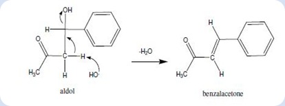
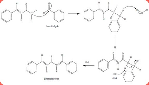
The oxygen attached to the benzylic position of carbon tends to attract one proton from water molecule to form hydroxide group in the intermediate. This is the formation of an aldol since the molecule consists of a carbonyl group and an alcohol group. In the basic condition, the hydroxide ion tends to remove one proton from the α-carbon resulting the formation of C=C double bond at the α and β carbon. At the same time, the hydroxide group attached to the β carbon forms a leaving group. After the condensation, benzalacetone was formed after two water molecules leaved as shown:

clip_image010

Diagram 3

The benzalacetone tends to form benzalacetone enolate ion after the hydroxide group from the surrounding attack the proton which attached to the carbon at benzylic position.

clip_image012

Diagram 4

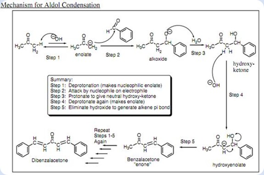
The same process has been take place as in the Diagram 2 but with the more bulky benzalacetone enolate ion as the material. The benzalacetone enolate ion acts as a nucleophile which attacks another benzaldehyde. The protonation of the aldol took place followed by the hydroxide groups have been eliminated as leaving groups. As a result, the nucleophilic addition and base-catalyzed dehydration lead to the formation of the desired product which is dibenzalacetone. The mechanism of dibenzalacetone formation was shown in the Diagram 5:

clip_image014


Diagram 5

The overall mechanism of the dibenzalacetone was summarized in the Diagram 7 as shown in below:

clip_image016

Diagram 7

The percentage yield of dibenzalacetone in this experiment is 83.27%. Some of the product has been lost during the process of recrystallization. In recrystallization, some of the product dissolved in the ethyl acetate. The melting point of the product is lower than the actual melting point (110 °C ~ 111 °C). This is because there is some impurities exist in the particular compound which will tend to lower the melting point of the dibenzalacetone.

Precaution steps:

1. Avoid to carry out the experiment near the fire since the organic solvent are mostly flammable.

2. Avoid to smell benzaldehyde directly.

3. Handle carefully with sodium hydroxide since it is corrosive.

Tuesday, November 8, 2011

Thin Layer Chromatography and Column Chromatography

Objective:

Part I:

1. To learn the technique of TLC and the visualization of colourless components.

2. To identify an unknown drug by a TLC comparison with standard compounds.

Part II:

1. To learn the technique of column chromatography.

2. To separate the mixture of pyrene and p-nitoraniline by column chromatography.

Introduction:

Chromatography is a common laboratory technique to separate and analyze two or more analytes in the mixture by distribution of two phases: a stationary phase and a mobile phase. The stationary phase is a phase which allows the mobile phase to travel along. These two phases can be solid-liquid, liquid-liquid or gas liquid. This method works on the principle that different compounds with different solubilities and adsorptions to the two phases which they are to be partitioned. The compounds to be retained on the stationary phase are more interacted with it while the compounds to be moving carried along by the mobile phase. The rates of migration for each component on the system is depends on the degree of the compounds of mixture are adsorbed by the stationary phase and their degree of solubilities on the mobile phase. The stronger the adsorption by stationary phase, the slower the compounds travels along the mobile phase. As a result, the distance of separation for each compound in the mixture will be different. The types of chromatography is divided into few types which include gas chromatography(GC), high performance liquid chromatography(HPLC), thin layer chromatography(TLC), and column chromatography(CC). However, only TLC and CC are applied in this experiment.

Thin layer chromatography (TLC) is a solid-liquid form of chromatography where the stationary phase is usually a polar adsorbent while the mobile phase can be one single solvent or a combination of solvents. TLC is a quick and inexpensive technique that can be used to 1) determine the number of compounds in a mixture, 2) identify the compounds, 3) monitor the progress of a reaction, 4) determine the effectiveness of a purification, 5) determine the appropriate conditions for column chromatography separation, and 6) analyze the fractions obtained from column chromatography. In thin layer chromatography, the stationary phase is refers to polar adsorbent, usually is silica gel or aluminium oxide which is coated on an aluminium plate. Generally, polar solvent is used as the mobile phase in the system to carry the analytes by passing through the stationary phase. The stationary phase in TLC chromatography is typically silica gel, (SiO2.xH2O)n which has been shown in the diagram 1 below:

image Diagram 1

Different compounds are spotted on the silica gel plate (stationary phase), the prepared solvent (mobile phase) will carry the compounds goes up along the plate through capillary action which the solvent travels from the bottom to the solvent front. Once the dilute solutions of compounds are spotted on the plate, then development of solvent is the next. After that, the position of each compounds can be visualized under the presence of ultraviolet (UV) light. The compounds in the mobile phase will have different interaction with the polar stationary phase. The factors are mainly depends on the polarity of adsorbent (silica gel in this experiment), solvent polarities, and functional groups of the compounds. The polar adsorbent will more strongly attract the polar molecules of compounds and it will have lower affinity to the non-polar compounds. Hence, the movement of compounds with different polarities could be different. In addition, the polarity of solvent is very important to the compound separations, a solvent system may increase in its polarity by changing the composition of the solvent mixture. The more polar the solvent, the faster the compounds can be drawn up, which means the further the compounds move. The comparison of the polarities of solvent are listed down in the diagram 2.

image Diagram 2

The second factor that affects the interaction between stationary phase and compounds is functional group of each compound. The highly polar groups in compound will cause the stronger adsorption and eluted less readily to the stationary phase compared to less polar compounds. Hence, the highly polar compounds will tend to interact strongly with the polar adsorbents and absorb onto the fine particles of the absorbent, hence it cannot travel further. The adsorption strengths of each compound having the following types of functional groups in the order of increasing group polarities.

image However, the variation may take place which depends on the overall structure of each compound.

Column chromatography is one of the most useful methods for the separation and purification of both solids and liquids when carrying out small-scale experiments. Like TLC, the silica gel is used as a stationary phase while an organic solvent is used as the mobile phase which its polarity should be lower than silica gel. Column chromatography is carried out in a glass tube that is clamped vertically with the mixture of samples at the top. The samples are dissolved in a small quantity of solvent which is used to apply on the top of the vertical column. In this case, the solvent (mobile phase) will tend to flow down through stationary phase (silica gel) instead of the capillary action. The compound with less polar characteristics will elute faster through the column due to the silica gel has the strong affinity towards the more polar compounds. Eventually, the compounds start to be separated as the solvent is allowed to flow through the stationary phase. Due to the difference in their polarities, the solvent acts as the mobile phase will carry the less polar compounds further down from the top in the system. Below the column, several flasks are used to collect the solvent with compound in various fractions. The solvent is continually added to the top of the column until each band resolves and is carefully collected. As a result, the experiment is end up with the separation of two compounds from the mixture into two different portions. With coloured substances, the bands might be visible and easily to be collected as they run off the column. However, colourless compounds can be observed directly. So, the particular compound in eluting solvent is collected in many small fractions and testing each of them by using TLC. A fresh solvent (mixture of solvent similar to the eluent in column chromatography) is being used in TLC for the next step of identifying the compounds.

The total distance traveled by the compounds on silica gel plate are measured and is being compared to each other. The migration rate of each compound is compared by using the retardation factor, Rf. Retardation factor is the ratio of distance traveled of the compound to the distance of the solvent traveled. Retardation factor, Rf is the distance of compound traveled divided by the total distance of solvent travelled in TLC plate. If two spots in the TLC plate travel the same distance or have the same value of Rf, then both compounds might be concluded as the same compounds.

Part I: TLC analysis on analgesics drugs

Apparatus: UV lamp, capillary tube, 250ml beaker

Materials: aspirin, acetaminophen, caffeine, unknown A, unknown B, TLC plates, ethyl acetate, hexane, iodine

Procedure:

PartA: Spotting the TLC plate

1. A TLC plate was obtained from instructor. Holding the edges of the plate carefully.

2. Set the plate down on a clean and dry surface, then a line was drawn across the plate about 1.0cm from the bottom of the plate by using a 2B pencil.

3. Five lines of 2-3mm were drawn, spaced about 0.6cm apart and running perpendicularly through the lines across the bottom of the TLC plate. 0.5cm must be spaced from each side of the edges.

4. 5 different analgesics were spotted on each 2-3mm lines. Firstly, acetaminophen was spotted on the plate, followed by caffeine, unknown A, aspirin and lastly the unknown B. The plate was examined under the UV light to check whether enough each solution has been applied.

Part B: Developing the TLC plate

1. A developing chamber was prepared by using a 250ml beaker, a half-piece of filter paper inside and aluminium foil to cover.

2. Mixture of 1:3 of ethyl acetate : hexane was poured into the beaker to the depth of about 1cm. The TLC plate was placed in the developing chamber.

3. After the solvent has risen to near the top of the plate, the plate was removed.

Part C: Visualization

1. The colourless compounds were visualized by illumination of the plate with UV lamp.

2. The spots were outlined by using a 2B pencil. The spots may be visualized by putting the plate in an iodine chamber for a couples of minutes.

Part D: Comparison of the unknown with reference standards

1. The plate was sketched in notebook and the Rf value was calculated for each spot.

2. The unknown drug was determined based on Rf value.

Part II: The separation of pyrene and p-nitroaniline by column chromatography

Apparatus: glass column, UV lamp, capillary tube, 250ml beaker, test tubes, glass funnel

Materials: pyrene, p-nitroaniline, TLC plates, ethyl acetate, hexane, iodine

Procedure:

Part A: Column preparation

1. A 49cm chromatography column, 15g of deactivated Silica gel and 110ml of developing solvent mixture (ethyl acetate:hexane; 1:3) were obtained.

2. A slurry of the adsorbent( silica gel) was prepared with a solvent in a 250ml Erlenmeyer flask.

3. A small plug of cotton was pushed into the constriction at the bottom of the column. The column was clamped in a vertical position and 0.5cm layer of the sodium sulfate anhydrous was added on top of the cotton.

4. Ensuring the stopcock of the column is closed, 15ml of solvent was poured in. After setting, all the slurry was quickly decanted through a funnel into the column.

5. The stopcock was opened and allowed the solvent to drain while tapping the walls of the column with the ends of a folded price of rubber tubing.

6. Once the solvent level is within 6cm of the top of the adsorbent, the packing should be essentially complete. 0.5cm level layer of sodium sulfate anhydrous was added on the adsorbent.

7. Excess solvent was drain off until its level is precisely on top of the sodium sulfate anhydrous and the stopcock was closed.

Part B: Separation and collection of pyrene and p-nitroaniline

1. The mixture of pyrene and p-nitroaniline was took and a few drops of ethyl acetate was added to dissolve as much as possible.

2. The solution was transferred directly to the top of the sulfate anhydrous layer with a dropper.

3. The solvent was drain off until the mixture solution is just below the top of the sodium sulfate anhydrous.

4. The wall was rinse with 1ml of fresh solvent(ethyl acetate/hexane 1:3) and was drain until the level was once again below the top of sodium sulfate anhydrous. The rinsing of the walls was repeated until the solvent above the silica gel is virtually colourless.

5. The column was filled carefully with the fresh solvent(ethyl acetate/hexane 1:3) and allowed solvent to drain.

6. The separation of bands was observed as the column develops. The colourless band of pyrene was collected into 3 test tubes.

7. When the edge of the yellow band (p-nitroaniline) reached the lower part of column, a new test tube was replaced and the yellow band was collected into three fractions.

8. Each fraction was concentrated to a small volume by evaporation for analysis by TLC.

Part C: Analysis of the fraction

1. The fractions were spotted on a TLC silica gel plate along with the reference pyrene and p-nitroaniline.

2. The TLC plate was developed in a developing chamber containing a mixture of ethyl acetate/hexane 1:3.

3. The TLC plate was visualized with the UV lamp to determine the fraction of pure pyrene and pure p-nitroaniline.

4. The chromatogram was drawn in the notebook.

5. The Rf value was calculated for pyrene and p-nitroaniline.

6. The pure fraction of pyrene was combined in a pre-weigh test tube and the pure fraction of p-nitroaniline in another test tube. Both solvents were evaporated on a stem bath.

7. Once the solvent has evaporated, the weight of the pure pyrene and p-nitroaniline were calculated.

Results:

Part I:

Total distance of solvent travelled from bottom line in TLC plate = 8.0cm

Retardation factor, Rf

= Distance of sample travelled from the bottom line / Total distance of solvent travelled from bottom line in TLC plate
 

Samples

Distance travelled from the bottom line (cm)

Retardation factor, Rf

Acetaminophen

0.50cm

0.0625

Caffeine

0.35cm

0.0438

Unknown A

0.50cm

0.0625

Aspirin

2.40cm

0.3344

Unknown B

2.20cm

0.2750

Diagram of acetaminophen, caffeine, unknown A, aspirin, and unknown B travelled on the TLC plate

image Inference: unknown A is acetaminophen whereas the unknown B is aspirin.

Part II:

Total distance of solvent travelled from bottom line in TLC plate = 8.0cm

Retardation factor, Rf

= Distance of sample travelled from the bottom line / Total distance of solvent travelled from bottom line in TLC plate
 

Samples

Distance travelled from the bottom line (cm)

Retardation factor, Rf

1st fraction of pyrene

6.1cm

0.7625

2nd fraction of pyrene

6.1cm

0.7625

3rd fraction of pyrene

6.1cm

0.7625

4th fraction of pyrene

6.1cm

0.7625

1st fraction of p-notroaniline

1.6cm

0.2000

2nd fraction of p-notroaniline

1.7cm

0.2175

3rd fraction of p-notroaniline

1.7cm

0.2175

4th fraction of p-notroaniline

1.7cm

0.2175

Diagram of pyrene and p-nitoraniline travelled on the TLC plate
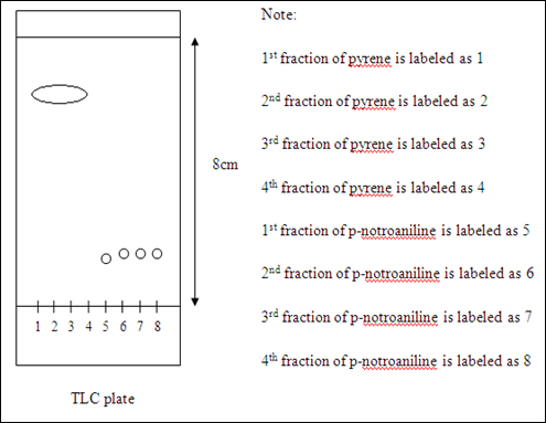
image Inference: pyrene is present in the 1st to 4th spots while 5th to 8th spots containing p-nitroaniline.

Discussion:

In the thin layer chromatography, the eluent (solvent) is prepared by using a mixture of hexane and ethyl acetate in the ratio of 3:1. The polarity of the particular solvent cannot be too low because the polar compounds will not be able to carry by the eluent and will not be separated, so that the separation might not be observable. If the solvent of too high polarity is used, the polar compound will travel so fast that the separation between non-polar compound and polar compound to become so small and poor separation will be observed. The solvent mixture of ethyl acetate and hexane (1:3) is believed that it has the optimized solubility for the organic compounds to dissolve in the solvent. In another word, the compounds can be easily to be carried by the solvent in the TLC plate. A few drops of acetic acid were added into the particular solvent in order to protonate the organic compound on the TLC plate and prevent them from ionization. This is due to the deprotonation of organic compounds will cause the compound to form ions. So, the adding of acetic acid is used to maintain the structure of organic compound as they can travel up through the TLC plate. Before the TLC plate is placed into the solvent. A filter paper was dipped inside the solvent in a beaker which is covered by using an aluminium foil. This is to create a system that prevents the vapourization of organic solvent and hence the solvent is allowed to travel up along the plate faster. After the TLC plate was introduced into the solvent, the solvent is starting to migrate itself and the compounds on the TLC plate until the solvent front has been reached.

There are three components in the TLC which include the TLC plate with adsorbent, the development solvent and the organic compounds that to be analyzed. The adsorbent, silica gel consists of a three dimensional network of thousands of alternating silicon and oxygen bonds. It is a very polar and is capable of hydrogen bonding due to its partial positive charge in silicon and partial negative in oxygen. The silica gel with compete with the development solvent for the organic compounds as the solvent is traveling up through the TLC plate. The silica gel tends to bind the compounds (on stationary phase) while the development solvent tried to dissolve the compounds (on mobile phase) in order to carry the compounds along the plate as the solvent travels up. All the compounds are possible to be adsorbed into the stationary phase however the time of adsorption of compounds in the particular phase is depends on the polarity of each compound. The more polar the compound is, the longer the time taken that the compound adsorbed into the stationary phase so it eluting speed is slower (more time on stationary phase). Less polar compounds are weakly adsorbed, so the time taken for less polar compounds to be adsorbed on stationary phase is shorter. As a result, the less polar compounds can travel further along the plate compared to the more polar compounds.

In this experiment, the analgesics drugs have been analyzed by using TLC are acetaminophen, caffeine, and aspirin. The structure of each compounds are shown as below:
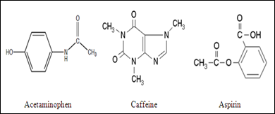
imageThe polarity of the compounds could be compared by looking at the structure of these compounds. The polarity of the compound is due to the effect of electronegativity in atoms and the asymmetrical structure of compound. The unequal sharing of electron within the bond causes the formation of an electric dipole which leads to partial positive and partial negative exist in the several atoms. The highly electronegative atoms present in these compounds are O, N, and F. These highly electronegative atoms tend to withdraw the electrons towards themselves from the aromatic ring and hence it polarizes the compounds. Nitrogen and oxygen atom present in these compounds have higher electronegativity compared to the carbon atom and hydrogen atom. Thus, nitrogen and oxygen atom acquire partial negative charge while the carbon and hydrogen atom acquire partial positive charge. Hence, caffeine has the highest polarity, followed by acetaminophen while aspirin possesses the lowest polarity. The sequence of increasing in polarity is arranged in the order below:image 

Based on the retardation factor, Rf, the polarities of these compounds can be compared. The higher the Rf, the lower the polarity and hence the distance traveled by the compound would be longer. Aspirin has the highest Rf value. The interaction between aspirin and stationary phase (silica gel) is the weakest which allows the aspirin can travels up along the plate fastest. A stronger interaction in between the silica gel and acetaminophen causes the compound move slower when travels up the TLC plate. The polarity of the acetaminophen is considered lower than caffeine but the difference is quite small. This can be shown in the distance traveled by both compounds which corresponding to their Rf value. In this part, TLC method can be used to identify the two unknowns spotted on the TLC plate. The compounds with same polarities usually travel up through the plate in the same distance and possess the same Rf value provided the stationary phase and mobile phase are identical. Unknown A is predicted as acetaminophen while unknown B is forecasted as the aspirin. This is because the Rf value of unknown A and unknown B are same with the Rf value of acetaminophen and aspirin respectively.

Column chromatography is used to purify the individual organic compound from the mixture of compounds. In column chromatography, the stationary phase and mobile phase used are same as used in thin layer chromatography. The adsorbent (stationary phase) used is a solid which silica gel is usually being used. The eluent (mobile phase) used is the mixture of hexane and ethyl acetate in the ratio of 1:2. The compounds used were the pyrene and p-nitroaniline. The structure of each compound are shown as below:image Based on the structure of the compound, the pyrene has the lower polarity due to its delocalized electron in the aromatic ring. The delocalizing π electrons are distributed evenly in the whole structure and hence it stabilize the pyrene. In addition, there is no other electronegative atom attach to the pyrene as substituent, so the electron are just delocalize within the four aromatic ring of pyrene. On the other hand, the p-nitroaniline has higher polarity due to its electronegative substituent in the structure. N and O atoms are the highly electronegative atoms which tend to withdraw the electrons from the benzene ring towards the atoms. This causes the arisen of partial positive charge and partial negative charge in the substituent and within the benzene ring. Consequently, the structure of p-nitroaniline induces the polar property of the compound and hence the polarity of p-nitroaniline is much more higher than pyrene. Due to the difference in polarities in each compound, the interaction with the silica gel would be different. The polar compound would have the stronger interaction with the silica gel. This is because the polar silica gel tends to pull the polar p-nitroaniline toward the stationary site and causes the compound becomes more difficult carried by the solvent through the system. As a comparison, the less polar pyrene was weakly adsorbed into the stationary phase. The silica gel would not tend to attract the less polar compound into the stationary site and hence the particular compound can be carried by the solvent to reach the bottom of the column. The pyrene is said that it elute faster than the more polar p-nitroaniline.
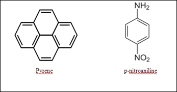
The total number of fraction have been collected was 19 fractions after all the yellow bands (p-nitroaniline) transferred out from the column. After evaporated most of the solvent, the 19 fractions were concentrated into eight fractions which each of the fraction have been used to apply on a TLC plate by using TLC. The separation of compounds is considered as successful since the 1st to 4th spots are containing pyrene only. The 5th to 8th spots are only contain the compound of p-nitroaniline. These can be proved by checking the distance of compounds traveled on TLC plate of each fraction and the corresponding to the R value are the same. However, the colours of the 1st and 4th fractions of pyreme on the TLC plate were faded compared to the 2nd and 3rd fractions. This might be due to the concentration of pyrene in the former fractions were not the same with the latter fractions. The amount of pyrene collected in the 1st fraction is less because it collected more solvent. The 4th fraction also has less concentration of compound because the concentration left in the column after 2nd and 3rd fractions of compound have been collected. The four spotted compounds were noticed that they were connected to each other on the TLC plate. This might be due to the diameter of the spotted place was too big. The 1st and 4th fractions of p-nitroaniline also have the same condition which their colours on the TLC plate were faded. It was believed that the 1st fraction and 4th fraction of p-nitroaniline have the similar condition with the 1st and 4th fractions of pyrene. The concentrations of the p-nitronaniline were not enough so they appear lighter colours on the plate under the sources of ultraviolet light.

By using the iodine as the development solvent in TLC, the similar observation for the both pyrene and p-nitroaniline were observed. The distance traveled of compounds were almost similar compared to previous solvent. But, the difference was just the colour of the spots on the TLC plate.

Precaution steps:

1. Do not move the beaker after the TLC plate had introduced into the beaker.

2. Do not look directly to the ultraviolet lamp.

3. Avoid to use pencil on the TLC plate

4. Do not touch on the surface of silica gel of TLC plate by using finger.